41++ Bosch throttle body wiring diagram ideas in 2021
Home » Wallpapers » 41++ Bosch throttle body wiring diagram ideas in 2021Your Bosch throttle body wiring diagram images are available. Bosch throttle body wiring diagram are a topic that is being searched for and liked by netizens today. You can Get the Bosch throttle body wiring diagram files here. Download all free vectors.
If you’re searching for bosch throttle body wiring diagram images information related to the bosch throttle body wiring diagram topic, you have come to the right blog. Our website always provides you with suggestions for viewing the highest quality video and image content, please kindly surf and find more informative video articles and images that match your interests.
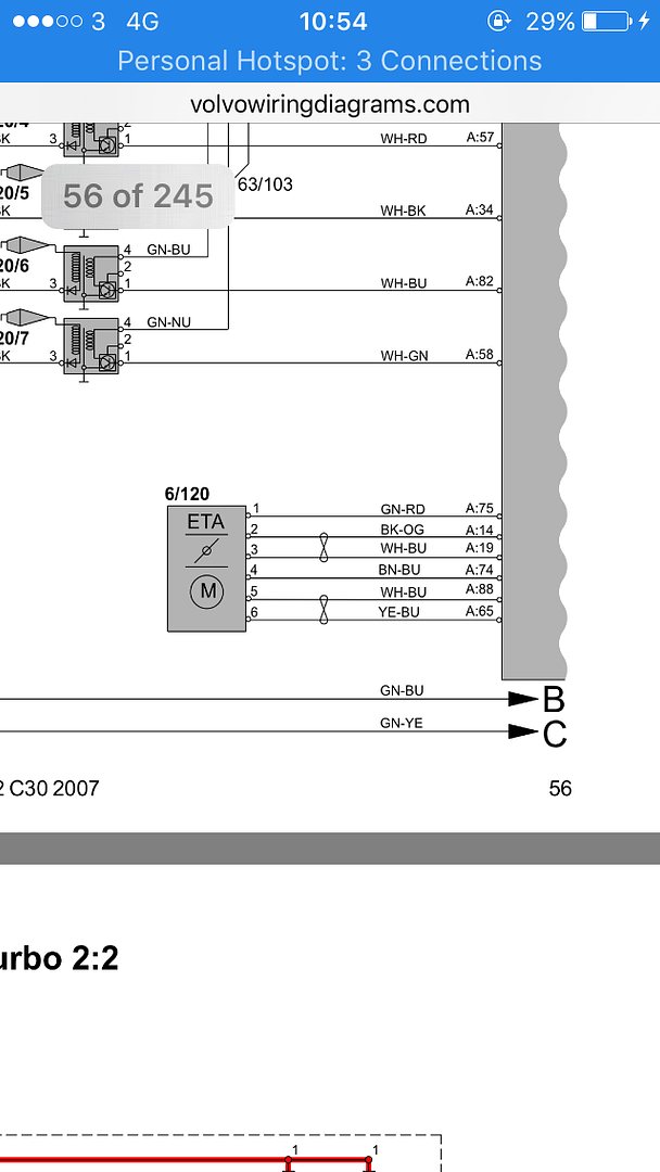
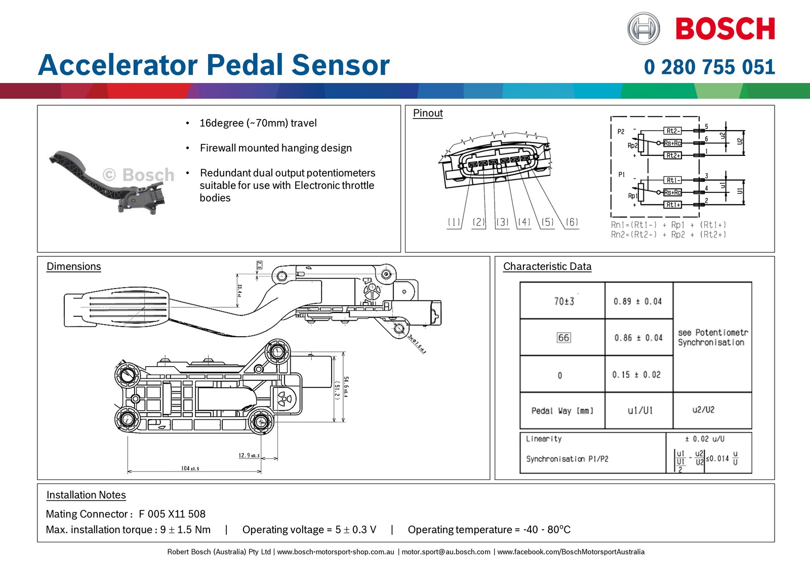
Bosch Throttle Body Wiring Diagram. Filthy Rich shows you how to save money by replacing a throttle plug wire instead of the whole throttle body assemblyFollow Rich on Twitter. Pin Outs - Dual Relay. Looking for some assistance for wiring the Bosch DBW throttle body 60mm bore diameter and Bosch accelerator pedal to suit - for Haltech Elite 2500 ECU. It is up to the user to ensure these are correct for their application.
 Electronic Throttle Wiring Test Youtube From youtube.com
Throttle Body Wiring Diagram wiring diagram is a simplified usual pictorial representation of an electrical circuit. Electronic Throttle Body 40 mm Part Number 0 280 750 149. Electronic Throttle Motor Wires Identification. Pin 2 B Poti -. Basically the maf sensoralso known as airflow metermeasures the amount of air flowing into the engine through the air cleaner assembly which contains the air filter and connects to the throttle body. Weld on flanges available also.
Here is a video on how you can test your maf sensor using a.
Electronic Throttle Body 40 mm Part Number 0 280 750 149. The wipers should always sum to 5V or you are limping home on one pot. Bosch Mx25 Wiring Diagram De. Throttle Position Sensor Wiring Diagram 1997 1998 Ford 4 6l 5 4l Repair Guides Repair Guides Circuit Diagram Throttle Position Sensor Placement And Wiring Junk Yard Zetec 1993 1995 Tps Wiring Diagram Jeep Grand Cherokee 4 0l Repair Guides 446 4 Wire Throttle Position Sensor Diagram Wiring Resources. The idea is to run one 0 to 5V clockwise and the othe 5V to 0 clockwise. ETB applications with flex-fuel CNG and LPG are permissible if injec-ted in the air flow after the throttle body.
 Source: youtube.com
Adjustment of the IA has no effect on mixture when the throttle is open. Electronic Throttle Body 32mm bore SKU. It shows the components of the circuit as simplified shapes and the capability and signal associates along with the devices. The idea is to run one 0 to 5V clockwise and the othe 5V to 0 clockwise. 0 280 750 148 Typically ships in.
 Source: forums.haltech.com
Throttle Body Wiring Diagram wiring diagram is a simplified usual pictorial representation of an electrical circuit. Idle Adjustment Screw and Locking Nut in Throttle Body. Genuine Bosch Motorsports 82mm Electronic Throttle Body. EFAW 228 Bosch pn 0 681 500 001 D-Jet tester. Electronic Throttle Body 32mm bore SKU.
 Source: vpcuk.org
This is standard procedure in every safety critical drive by wire throttle system. Bosch Mx25 Wiring Diagram De. Download our wiring diagrams for our complete range of Bosch controls and modules. Adjustment of the IA has no effect on mixture when the throttle is open. The wipers should always sum to 5V or you are limping home on one pot.
 Source: avrfreaks.net
Pin 4 D Motor. In combination with the electronic throttle control system the throttle body assembly is designed to control the amount of fresh air entering the engine. Before replacing the throttle control actuator and throttle body try cleaning the throttle plates and all plug-in wiring connections. Wiring Diagram Bosch L-Jetronic. Throttle valve switch I and II accelerator.
 Source: researchgate.net
Electronic Throttle Body 40 mm Part Number 0 280 750 149. Filthy Rich shows you how to save money by replacing a throttle plug wire instead of the whole throttle body assemblyFollow Rich on Twitter. Throttle Body Wiring Diagram wiring diagram is a simplified usual pictorial representation of an electrical circuit. If there is only one pot and a wire comes off somewhere you get zero or wide open throttle. Electronic Throttle Body 54 mm Part Number 0 280 750 150.
 Source: efihardware.com
Pin 4 D Motor. It is up to the user to ensure these are correct for their application. Electronic Throttle Body 50 mm Part Number 0 280 Y05 107-10. Übersetzungswechsel mit dem BOSCH MODAS-System eingestellt werden. A typical ETC system includes the following compon-ents.
 Source: researchgate.net
As can be seen in the 73 1800ES Fuel Injection Wiring Diagram above this component as well as the Cold. Adjustment of the IA has no effect on mixture when the throttle is open. Electronic Throttle Body 40 mm Part Number 0 280 750 149. Use Throttle Body Mode 6. Weld on flanges available also.
 Source: pinterest.com
Pin 3 C Poti. EFAW 228 Bosch pn 0 681 500 001 D-Jet tester. Pin 2 B Poti -. The idea is to run one 0 to 5V clockwise and the othe 5V to 0 clockwise. Adjustment of the IA has no effect on mixture when the throttle is open.
 Source: pinterest.com
From the Bosch website PDF it states the following Pin 1 A Motor -. You could also try checking the FG Boss 315 cal with the large oval throttle body which I believe is B8RH BBLH or B8LH not 100 which one it is. Suits common aftermarket Drive By Wire Throttle bodies including. Download our wiring diagrams for our complete range of Bosch controls and modules. Weld on flanges available also.
 Source: researchgate.net
The idea is to run one 0 to 5V clockwise and the othe 5V to 0 clockwise. Throttle valve switch I and II accelerator. Adjustment of the IA has no effect on mixture when the throttle is open. Electronic Throttle Body 50 mm Part Number 0 280 Y05 107-10. EFAW 228 Bosch pn 0 681 500 001 D-Jet tester.
 Source: researchgate.net
Also watch out the throttle body mounting bolts which can easily break use care when removing them. Download our wiring diagrams for our complete range of Bosch controls and modules. Also watch out the throttle body mounting bolts which can easily break use care when removing them. Suits common aftermarket Drive By Wire Throttle bodies including. Use Throttle Body Mode 6.
 Source: compsystems.com.au
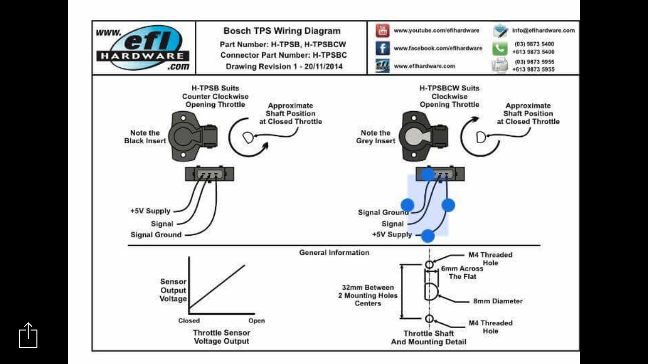
Before replacing the throttle control actuator and throttle body try cleaning the throttle plates and all plug-in wiring connections. Electronic throttle body accelerator pedal. From the Bosch website PDF it states the following Pin 1 A Motor -. Electronic Throttle Body 40 mm Part Number 0 280 750 149. Throttle Body 1 Butterfly Sensor 1 ECU TPS Input 2 5V 3 Butterfly Sensor 2 4 Signal GND 5 Motor 2 TC Pin 9 6 Motor 1 TC Pin 8 Connections shown looking at sensor Connections shown looking at body Connections are shown for information only.
 Source: pinterest.com
Electronic Throttle Motor Wires Identification. In combination with the electronic throttle control system the throttle body assembly is designed to control the amount of fresh air entering the engine. Illustrations descriptions and schematic drawings serve exclusively as hex screw MX25 plain washer. Looking for some assistance for wiring the Bosch DBW throttle body 60mm bore diameter and Bosch accelerator pedal to suit - for Haltech Elite 2500 ECU. A typical ETC system includes the following compon-ents.
 Source: efihardware.com
It is up to the user to ensure these are correct for their application. Electronic Throttle Body 40 mm Part Number 0 280 750 149. There are book on calibrating the pressure dropsurface area calcs for electronics throttle bodies you can read as well. Looking for some assistance for wiring the Bosch DBW throttle body 60mm bore diameter and Bosch accelerator pedal to suit - for Haltech Elite 2500 ECU. Adjustment of the IA has no effect on mixture when the throttle is open.
 Source: sau.com.au
It is up to the user to ensure these are correct for their application. This is standard procedure in every safety critical drive by wire throttle system. Bosch 32mm DBW Electronic Throttle Body 25300 AUD ex gst Bosch 54mm Electronic Throttle Body 22000 AUD ex gst Bosch 60mm DBW Electronic Throttle Body 22000 AUD ex gst Bosch 68mm DBW Electronic Throttle Body 24000 AUD ex gst. The wipers should always sum to 5V or you are limping home on one pot. Great for custom applications when a large throttle body is required.
 Source: ebay.com
Electronic Throttle Body 40 mm Part Number 0 280 750 149. 0 280 750 148 Typically ships in. This is standard procedure in every safety critical drive by wire throttle system. Suits common aftermarket Drive By Wire Throttle bodies including. Before replacing the throttle control actuator and throttle body try cleaning the throttle plates and all plug-in wiring connections.
 Source: axleaddict.com
Great for custom applications when a large throttle body is required. As can be seen in the 73 1800ES Fuel Injection Wiring Diagram above this component as well as the Cold. Before replacing the throttle control actuator and throttle body try cleaning the throttle plates and all plug-in wiring connections. Filthy Rich shows you how to save money by replacing a throttle plug wire instead of the whole throttle body assemblyFollow Rich on Twitter. Use Throttle Body Mode 6.

Throttle Body Wiring Diagram wiring diagram is a simplified usual pictorial representation of an electrical circuit. Download our wiring diagrams for our complete range of Bosch controls and modules. This is standard procedure in every safety critical drive by wire throttle system. Bosch Motorsport Drive By Wire throttles for performance and motorsport applications. A typical ETC system includes the following compon-ents.
This site is an open community for users to do sharing their favorite wallpapers on the internet, all images or pictures in this website are for personal wallpaper use only, it is stricly prohibited to use this wallpaper for commercial purposes, if you are the author and find this image is shared without your permission, please kindly raise a DMCA report to Us.
If you find this site value, please support us by sharing this posts to your own social media accounts like Facebook, Instagram and so on or you can also save this blog page with the title bosch throttle body wiring diagram by using Ctrl + D for devices a laptop with a Windows operating system or Command + D for laptops with an Apple operating system. If you use a smartphone, you can also use the drawer menu of the browser you are using. Whether it’s a Windows, Mac, iOS or Android operating system, you will still be able to bookmark this website.
Category
Related By Category
- 44+ Boat trailer wiring diagram 4 wire info
- 16++ Boat lift switch wiring diagram info
- 46++ Battery wiring diagram for club car information
- 43++ Boss plow wiring diagram plow side ideas
- 36++ Bmw e90 wiring diagram pdf ideas
- 41+ Bmw e46 wiring diagram pictures ideas in 2021
- 25++ Boat trailer wiring diagram 5 wire info
- 38++ Boat light switch wiring diagram ideas
- 13++ Briggs and stratton charging system wiring diagram information
- 25++ Boss plow solenoid wiring diagram ideas