23+ Beats aux cord wiring diagram ideas
Home » Wallpapers » 23+ Beats aux cord wiring diagram ideasYour Beats aux cord wiring diagram images are available in this site. Beats aux cord wiring diagram are a topic that is being searched for and liked by netizens today. You can Find and Download the Beats aux cord wiring diagram files here. Find and Download all free photos.
If you’re searching for beats aux cord wiring diagram pictures information related to the beats aux cord wiring diagram topic, you have pay a visit to the right blog. Our website always provides you with hints for seeking the maximum quality video and image content, please kindly search and find more informative video content and graphics that fit your interests.
Beats Aux Cord Wiring Diagram. Remote Microphone Volume Control Talk Home Shop Beats Accessories Beats Aux Purple Cable1499 35mm gold-plated male jack tangle-free one straight one L-shaped This replacement purple aux cable for the Beats headphones features 35mm jacks on each end to easily connect to your phone and your headphones. Plug the matching cables coming from your turntable in the phono jacks. From the diagram below of a TRRS jack each of the arrows on the symbol corresponds to one of the Tip Ring 1 Standard mm jack pinouts. Parts for this repair httpbitly2vo6Jt7Written Repair Guide httpsbitly2TpI7xqJoes has fixed thousands of Beats Solo 2 Wired with the internal.
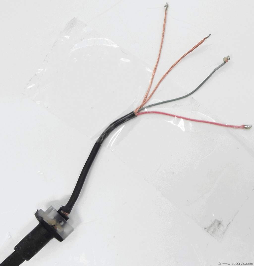 Beats Ep Wire Replacement Repair From petervis.com
Download aux cord 3 wire diagram epub. Sometimes you can see a copper wire. From the diagram below of a TRRS jack each of the arrows on the symbol corresponds to one of the Tip Ring 1 Standard mm jack pinouts. Plug the matching cables coming from your turntable in the phono jacks. Sub 1 -. Dark Green Brown.
Wireless headphones Beats studio 3 wireless Beats.
Stereo wiring diagram sony MHC EC99i. 3 CD changer audio signal earth. Using a pair of wire strippers you have to strip back the shielding of the wire on both sides. Sub 2 -. The SPD Speed Sensor wire is located on Pin4 and the PKB Park Brake wire is located on Pin15 as shown below. It shows how the electric cords are.
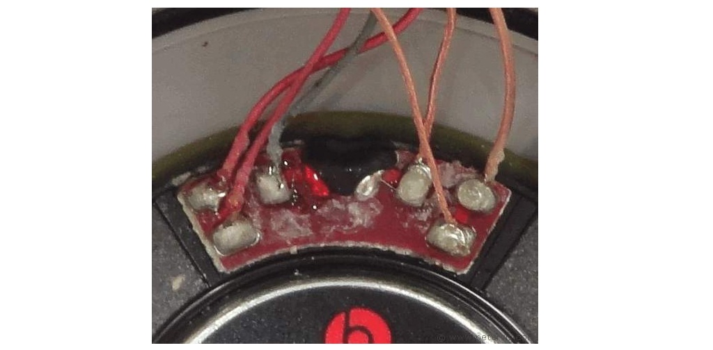 Source: petervis.com
Sub 1. As the title mentions I was wondering if anyone out there could help me with the understanding of the urbeats in-ear earbuds. Sub 1. Not only do they know their business but they probably use Marinco electrical products as well. Urbeats beats by drdre wiring Hi all First off sorry if this is the incorrect subreddit if anyone can suggest where I should go that would be greatly appreciated.
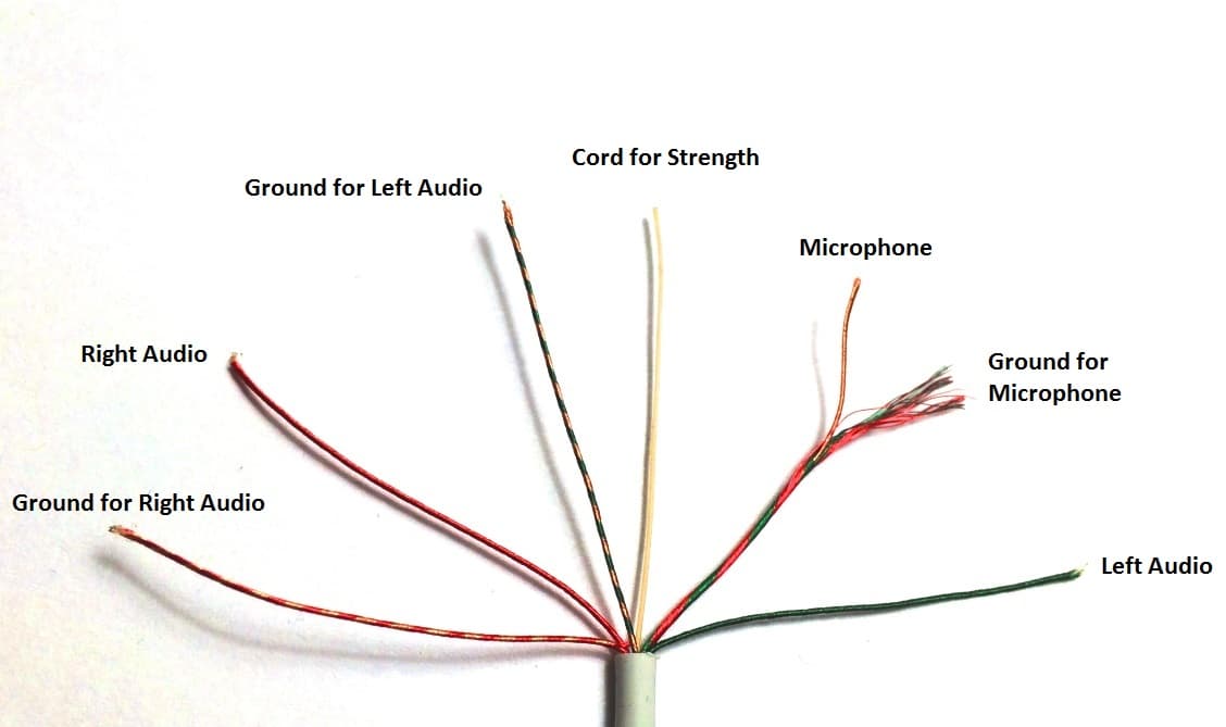 Source: circuitbasics.com
A third arrow as opposed to a wire joining to the sleeve the rectangle. 99 Replacement Audio Cable Cord Wire with in-line Microphone and Control OEM Replacement Leather PouchLeather Bag for Beats by Dr Dre Headphones SoloStudioProDetoxWirelessMixrExecutive. A wiring diagram is a basic aesthetic depiction of the physical links and physical layout of an electric system or circuit. A third arrow as opposed to a wire joining to the sleeve the rectangle. Wireing diagram for aiwa home stereo speakers.
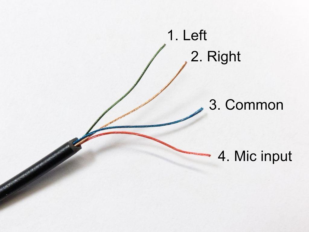 Source: bonek.yenpancane.jeanjaures37.fr
Parts for this repair httpbitly2vo6Jt7Written Repair Guide httpsbitly2TpI7xqJoes has fixed thousands of Beats Solo 2 Wired with the internal. Anyways if anyone needs it attached I put it in a zip file since it was too large of a PNG is the wiring diagram for the Beats System from my 2014 RT Now the zip file with the wiring is. Sub 1 -. Plug the matching cables coming from your turntable in the phono jacks. OEM Replacement AUX Audio Cable Cord For Beats By Dre Headphones Solo23StudioProWireless with Mic WhiteDiscontinued by Manufacturer with Storage Bag 4 out of 5 stars 13 899 8.
 Source: youtube.com
Download aux cord 3 wire diagram epub. 1 AUX signal input left. Sub 1. Wireless headphone pdf manual download. This should work for anything that has xm.
 Source: youtube.com
3 CD changer audio signal earth. When and also The best ways to Make Use Of a Wiring Diagram. If youre hooking your vintage turntable to a stereo receiver or amplifier that has jacks on the back marked PHONO its easy. Multi-pin connector 4 12-pin for CD changer control and CD audio input signals. Electrical wiring jvc car stereo wire harness diagram audio wiring head unit p jvc radio wire harness 81 wiring diagrams.
 Source: amazon.com
First things first the simple setup. If not the structure wont work as it should be. Dark Green White. First things first the simple setup. Sub 1.
 Source: aliexpress.com
Sub 2 -. 5 Not assigned. Sub 1 -. Stereo wiring diagram sony MHC EC99i. 3 CD changer audio signal earth.

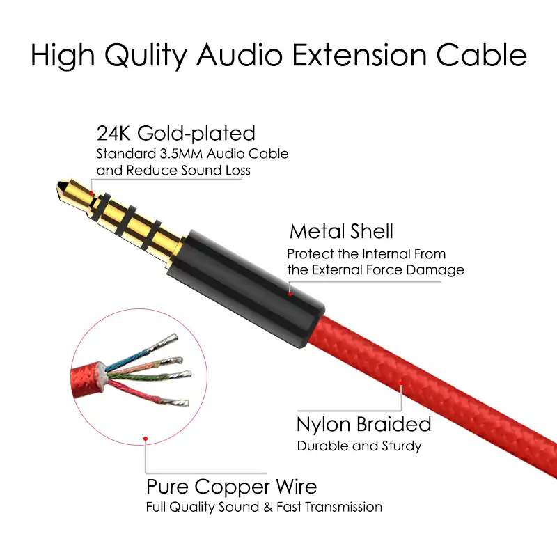
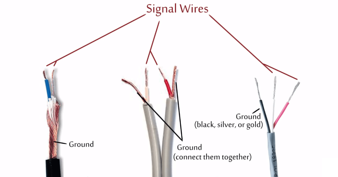
4 CD changer voltage supply positive terminal 30 contact continuous load greater than 1 A temporary peak load 5 A. If youre hooking your vintage turntable to a stereo receiver or amplifier that has jacks on the back marked PHONO its easy. This is where it becomes trial and error whether you connect the red if you get the headphones to work first before working out how the microphone connects at least youll know which connector ring is the common. To make sure that the color-coded wiring diagram below is not confusing start by soldering the copper wire that you twisted into a single wire to the contact that would be closest to the device when the jack is plugged in then the red wire the green wire and finishing with the red and green wire being soldered to the pole that sticks off of the back of the jack. 2655 Napa Valley Corporate Drive Napa California 94558 Phone.
 Source: youtube.com
Provides a plug-n-play connection at the vehicles original amplifier location. View and Download Beats Electronics Wireless user manual online. 2655 Napa Valley Corporate Drive Napa California 94558 Phone. Wireless headphone pdf manual download. Sub 1.
 Source: youtube.com
Multi-pin connector 4 12-pin for CD changer control and CD audio input signals. Sub 1. Beat Headphones have a different construction. Multi-pin connector 4 12-pin for CD changer control and CD audio input signals. You might see a different wire scheme.
 Source: 1994-chevys.losdol2-cabik.jeanjaures37.fr
Stereo wiring diagram sony MHC EC99i. Electrical wiring jvc car stereo wire harness diagram audio wiring head unit p jvc radio wire harness 81 wiring diagrams. View and Download Beats Electronics Wireless user manual online. Wireing diagram for aiwa home stereo speakers. Each component ought to be placed and linked to different parts in specific way.
 Source: playyourbeat.com
Stereo Headphone Jack Wiring Diagram 35 mm stereo female jack wiring diagram 35 mm stereo jack socket wiring diagram 35 mm stereo jack wiring diagram 4 pole Every electrical structure consists of various distinct pieces. Sub 1. You should be able to see three different wire colors. From the diagram below of a TRRS jack each of the arrows on the symbol corresponds to one of the Tip Ring 1 Standard mm jack pinouts. Most likely but not always theres also a skinny single wire coming from the turntable.
 Source: petervis.com
A wiring diagram is a basic aesthetic depiction of the physical links and physical layout of an electric system or circuit. Using a pair of wire strippers you have to strip back the shielding of the wire on both sides. Sub 1. Multi-pin connector 4 12-pin for CD changer control and CD audio input signals. Headphone Wiring Diagram Red Yellow Blue.
 Source: joesge.com
Not only do they know their business but they probably use Marinco electrical products as well. 3 CD changer audio signal earth. Anyways if anyone needs it attached I put it in a zip file since it was too large of a PNG is the wiring diagram for the Beats System from my 2014 RT Now the zip file with the wiring is. Parts for this repair httpbitly2vo6Jt7Written Repair Guide httpsbitly2TpI7xqJoes has fixed thousands of Beats Solo 2 Wired with the internal. To make sure that the color-coded wiring diagram below is not confusing start by soldering the copper wire that you twisted into a single wire to the contact that would be closest to the device when the jack is plugged in then the red wire the green wire and finishing with the red and green wire being soldered to the pole that sticks off of the back of the jack.
 Source: petervis.com
Cut the PKB wire Red with Black Stripe and connect the wire on the connector side to chassis ground. Cut the SPD wire White with Red Stripe and insulate the wire ends to prevent accidental contact. Cut the PKB wire Red with Black Stripe and connect the wire on the connector side to chassis ground. You should be able to see three different wire colors. Usb cord wire diagram have some pictures that related each other.
 Source: amazon.ae
As the title mentions I was wondering if anyone out there could help me with the understanding of the urbeats in-ear earbuds. Easily add amplifiers without cutting or modifying the vehicles original wiring. Multi-pin connector 4 12-pin for CD changer control and CD audio input signals. As the title mentions I was wondering if anyone out there could help me with the understanding of the urbeats in-ear earbuds. Most likely but not always theres also a skinny single wire coming from the turntable.
 Source: circuitbasics.com
Major modifications are called for nothing beats a qualified marine electrician. Wireing diagram for aiwa home stereo speakers. This should work for anything that has xm. Provides a plug-n-play connection at the vehicles original amplifier location. View and Download Beats Electronics Wireless user manual online.
 Source: youtube.com
1 AUX signal input left. This should work for anything that has xm. Most likely but not always theres also a skinny single wire coming from the turntable. To make sure that the color-coded wiring diagram below is not confusing start by soldering the copper wire that you twisted into a single wire to the contact that would be closest to the device when the jack is plugged in then the red wire the green wire and finishing with the red and green wire being soldered to the pole that sticks off of the back of the jack. If not the structure wont work as it should be.
This site is an open community for users to share their favorite wallpapers on the internet, all images or pictures in this website are for personal wallpaper use only, it is stricly prohibited to use this wallpaper for commercial purposes, if you are the author and find this image is shared without your permission, please kindly raise a DMCA report to Us.
If you find this site serviceableness, please support us by sharing this posts to your own social media accounts like Facebook, Instagram and so on or you can also bookmark this blog page with the title beats aux cord wiring diagram by using Ctrl + D for devices a laptop with a Windows operating system or Command + D for laptops with an Apple operating system. If you use a smartphone, you can also use the drawer menu of the browser you are using. Whether it’s a Windows, Mac, iOS or Android operating system, you will still be able to bookmark this website.
Category
Related By Category
- 44+ Boat trailer wiring diagram 4 wire info
- 16++ Boat lift switch wiring diagram info
- 46++ Battery wiring diagram for club car information
- 43++ Boss plow wiring diagram plow side ideas
- 36++ Bmw e90 wiring diagram pdf ideas
- 41+ Bmw e46 wiring diagram pictures ideas in 2021
- 25++ Boat trailer wiring diagram 5 wire info
- 38++ Boat light switch wiring diagram ideas
- 13++ Briggs and stratton charging system wiring diagram information
- 25++ Boss plow solenoid wiring diagram ideas